Metal injection molding (MIM) is a metalworking process used to manufacture small, complex parts using powdered metal and plastic. MIM combines the design flexibility of plastic injection molding with the strength and integrity of machined metals. It enables the cost-effective fabrication of components with dimensions ranging from 1 gram to 500 grams.
The MIM process produces parts with excellent mechanical properties, precision tolerances, and smooth surface finishes. This makes MIM suitable for manufacturing small, complex, net-shape metal components at high volumes for industries like automotive, medical, aerospace, electronics, and more.
This guide provides a complete overview of the MIM process, its applications, advantages, design considerations, equipment, materials, post-processing, quality control, and cost analysis. It includes detailed tables and comparisons to help engineers, product designers, and procurement managers learn about and evaluate the MIM process.
Overview of the MIM Process
Metal injection molding combines plastic injection molding techniques with powder metallurgy processes. The basic steps in the MIM process are:
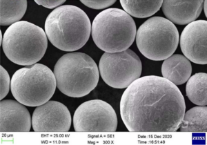
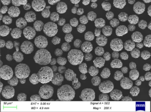
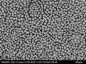
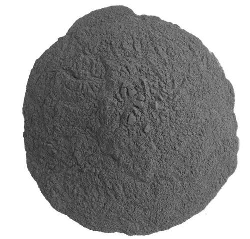
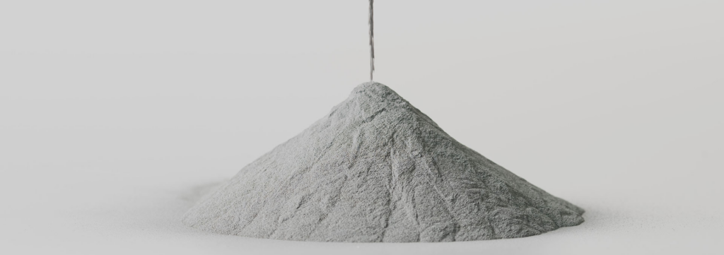
- Mixing: Mixing fine metallic powder with a plastic binder to create a homogeneous feedstock
- Injection molding: Heating and injecting the feedstock into a mold to form a shaped green part
- Debinding: Removing the plastic binder from the molded green part through solvent or thermal processes
- Sintering: Heating the debinded part to just below the melting point of the powder to densify the part through atomic diffusion and form a solid metal part.
The following table summarizes the key stages in the MIM process:
| Stage | Description |
|---|---|
| Mixing | Mixing fine metallic powder with binders into a homogeneous feedstock |
| Injection molding | Heating and injecting feedstock into a mold to form green part |
| Debinding | Removing binder through solvent or thermal processes |
| Sintering | Heating debinded part to densify powder and form metal part |
The MIM process produces consistent, high quality metal components suitable for high volume manufacturing. The process is highly repeatable and can create complex geometries with close tolerances not possible with other fabrication techniques.
Applications and Industry Usage of MIM Parts
MIM is used across many industries to manufacture small, complex, net-shape metal components with tight tolerances.
The following table outlines the major application areas and examples of parts made by MIM:
| Industry | Example Applications |
|---|---|
| Automotive | Gears, sprockets, rocker arms, connecting rods |
| Aerospace | Turbine blades, impellers, nozzles, valves |
| Medical | Orthodontic brackets, surgical instruments, implants |
| Electronics | Connectors, microgears, screens, printer nozzles |
| Firearms | Triggers, hammers, safeties, ejectors |
| Watches | Gears, pinions, watch hands |
MIM enables the production of small precision parts with complex geometries that would otherwise require extensive machining or other secondary operations. It offers design freedom, part consolidation, and weight reduction versus fabrication alternatives.
Advantages and Benefits of MIM
MIM provides several benefits over other small metal parts manufacturing processes:
Design Freedom
- Complex 3D geometries and shapes can be molded that are difficult or impossible with other methods.
- Intricate features like threads, cavities, and holes can be easily incorporated into MIM designs.
- Allows part consolidation and assembly reduction versus machining multiple components.
Precision and Tolerances
- Consistent dimensional precision and tolerances down to ±0.1% can be held using MIM.
- Fine details with good surface finishes down to 0.5 μm Ra are achievable.
Material Properties
- Sintered MIM parts typically reach 95-99% of the densities of wrought metals.
- Broad range of materials like stainless steel, tool steel, titanium alloys, tungsten alloys can be used.
- Excellent mechanical properties with the rigidity, strength, hardness, and wear resistance of molded metals.
Productivity and Costs
- High production rates possible with fast cycle times using MIM.
- Lower part costs than CNC machining for medium and high volumes.
- Lower costs than investment casting for complex, multi-component designs.
- Eliminates secondary machining operations required for fabricated metal components.
Sustainability
- Minimal material waste since MIM uses near net-shape processing.
- Powder metallurgy process with less energy usage than metal machining or casting.
- Allows lightweighting by optimizing geometries which reduces environmental footprint.
The following table summarizes the major advantages of MIM and compares it to other processes:
| Advantage | Comparison to Other Processes |
|---|---|
| Design freedom | More flexibility than machining or metal casting |
| Precision | Much higher than sand casting or die casting |
| Material properties | Approaches wrought metals unlike powder metallurgy |
| Productivity | Higher volumes than CNC machining |
| Cost-effectiveness | Lower costs than CNC machining or investment casting for medium+ volumes |
| Sustainability | Less waste than subtractive processes like CNC machining |
MIM combines the geometrical freedom of plastic injection molding with material properties close to fully dense metals. This empowers product designers to consolidate assemblies, optimize components, and manufacture intricate, high value metal parts at competitive costs.
Design Considerations for MIM Parts
Proper part design is critical for maximizing the benefits of the MIM process. Some key design considerations include:
Wall thicknesses – Moderate wall thicknesses between 0.8mm to 5mm recommended. Excessively thick or thin sections can lead to defects.
Tolerances – Precision tolerances of ±0.1% of dimensions are possible but allow for sintering shrinkage.
Surface finishes – Fine surface finishes under 1 μm Ra are possible depending on tool surface, geometries, and post-molding operations.
Geometry – Avoiding overly delicate geometries and maintaining structural integrity important to prevent defects. Minimal draft angles above 1-2° preferred.
Features – Holes down to 0.5mm diameter, threads, and complex internal features can be incorporated into MIM design.
Part Size – Smaller components between 0.5 grams to 500 grams are ideal for MIM processing. Larger parts may require CNC machining.
Assembly – Design for part consolidation by combining complex components and assemblies into single MIM parts.
Proper MIM component design optimizes manufacturability, minimizes defects, and leverages the key advantages of the MIM process. Consulting with MIM vendors during the design phase is highly recommended.
MIM Equipment and Tooling
Specialized equipment is used in the feedstock preparation, molding, debinding, and sintering steps of the MIM process:
Mixing and Feedstock Preparation
- Mixers – High intensity mixers for feedstock homogeneity
- Mills – Basket mills or roller mills for fine particle size reduction
- Temperature controllers – For regulating feedstock temperatures
- Degassing – Vacuum units for removing trapped air bubbles
Injection Molding
- Injection molding machines – Modified machines to handle MIM feedstocks
- Molds – Typically made of tool/stainless steels heat treated to withstand sintering
- Mold temperature controls – For regulating mold temperatures during molding
Debinding
- Solvent debinding chambers – For solvent extraction of binders
- Steam debinding autoclaves – For steam debinding processes
- Thermal debinding furnaces – For removing binders through thermal processes
Sintering
- Sintering furnaces – Vacuum, hydrogen, or nitrogen-based furnaces
- Atmosphere control systems – For regulating furnace atmospheres
- Temperature profiling controls – For executing optimized sintering cycles
Proper MIM equipment setup and calibration is vital for defect-free, high quality components. The injection molding stage requires the most specialized equipment like high temperature molds.
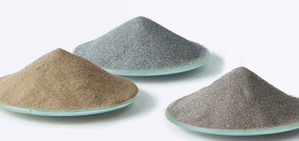
MIM Materials
A wide range of metals, alloys, and ceramics can be processed using MIM technology. Some of the common MIM materials include:
Metals
- Stainless steels (316L, 17-4PH, 410)
- Tool steels (H13, P20, D2)
- Low alloy steels (4140)
- Magnetic alloys
- Copper alloys
- Titanium alloys
- Tungsten heavy alloys
Ceramics
- Alumina
- Zirconia
- Silicon nitride
- Carbides
Material selection depends on factors like sintering temperatures, cost, mechanical and physical properties, and secondary processing needs. Stainless steel 316L is the most common MIM material due to its excellent sinterability.
The table below shows common MIM materials and their typical applications:
| Material | Applications |
|---|---|
| Stainless steel 316L | Surgical instruments, pumps, valves |
| Tool steel H13 | Injection molding, extrusion, dies |
| Titanium Ti-6Al-4V | Aerospace, medical implants |
| Tungsten heavy alloys | Radiation shielding, vibration damping |
| Copper alloys | Electrical contacts, thermal management |
| Ceramics | Cutting tools, wear parts, ballistics |
MIM enables the use of high performance materials like titanium and tool steel alloys in small, complex component designs. It expands the design possibilities for medical, aerospace, automotive, and industrial applications.
Post-Processing Operations
Secondary processing steps are often required after MIM sintering to achieve the final part:
- Annealing – Stress relieving heat treatment
- Hardening – Thermal hardening process like austempering
- Machining – CNC machining features like precision bore diameters
- Joining – Laser welding, soldering, or epoxy bonding sub-components
- Finishing – Plating, painting, passivation, or other surface finishing
The table below outlines common post-MIM processes and their purposes:
| Post-Process | Purpose |
|---|---|
| Annealing | Stress relief, ductility |
| Hardening | Improving hardness, strength |
| Machining | Critical dimensions and fits |
| Joining | Assembly of multi-part products |
| Finishing | Appearance, corrosion resistance |
Post-processing expands the options for property enhancements and precision machining. This further broadens the applicability of MIM across demanding applications.
Quality Control and Inspection
Consistent quality and dimensional control is critical for MIM components. Typical quality control tests include:
- Chemical analysis – For composition using optical emission or x-ray fluorescence spectroscopy
- Density measurements – Archimedes method or gas pycnometry to determine sintered density
- Mechanical testing – Hardness, tensile and fatigue properties per ASTM standards
- Microscopy – For microstructure, porosity, grain size, and defect analysis
- Dimensional analysis – Optical or CT scanning for dimensions and GD&T conformance
- Surface analysis – Roughness, corrosion, and coating tests as applicable
The following table outlines key quality tests conducted during different stages of MIM processing:
| Stage | Typical Quality Tests |
|---|---|
| Feedstock | Viscosity, torque, humidity |
| Green part | Dimensions, defect inspection |
| Debinding | Weight loss, residue |
| Sintering | Density, chemical assays |
| Finishing | Dimensions, microscopy, mechanical properties |
Comprehensive quality control and inspection at all steps of MIM are required to achieve defect-free components meeting application requirements.
Cost Analysis
The following factors determine the economics of the MIM process:
- Tooling – Die tooling has high initial costs depending on part geometries. Multiple cavities in tools spread costs over higher volumes.
- Set up – Significant initial machine settings and process development costs.
- Material – Powder metals represent 10-15% of total part cost. High for costly materials like titanium alloys.
- Labor – Some skilled labor needed but less than CNC machining. Lower at high volumes.
- Secondary Processing – Can significantly increase costs if extensive machining or finishing needed.
- Volume – Ideal for medium to high production volumes from 10,000 to millions of parts. Provides optimal cost advantage over other processes in this range.
The following table outlines indicative cost factors in MIM manufacturing:
| MIM Cost Component | Details |
|---|---|
| Tooling | $5,000 to $100,000+ depending on part complexity |
| Set Up | $10,000 to $50,000 for process development |
| Materials | 10-15% of part cost, higher for costly alloys |
| Labor | Lower contribution versus CNC machining |
| Secondary Processing | $2 to $20 per part depending on operations |
| Volume | Ideal for 10,000+ parts, lower cost than alternatives |
MIM provides a cost advantage over machining and casting for medium to high production volumes provided secondary processing is minimal. The process offers the highest economic benefits for complex, multi-component designs consolidated into a single MIM part.
Choosing a MIM Supplier or Partner
Selecting a competent MIM supplier is key to cost-effective production of high quality components. Some criteria for assessing MIM suppliers:
- Experience – Number of years in business and MIM expertise. Longstanding players tend to be more reliable.
- Materials –Variety of material offerings including key alloys needed. Nanopowder capabilities improve properties.
- Quality – Robust quality program and certifications like ISO 9001 and ISO 13485. Evidence of process controls.
- Tooling capabilities – Offering full tooling inhouse provides better cost integration and reduces issues.
- Secondary processing – Availability of complementary processes like CNC machining and finishing improves convenience.
- Prototyping – Capability for rapid prototyping in MIM reduces lead time and cost.
- R&D competence – Strong research and engineering expertise for process innovation.
Choosing an established supplier with broad in-house capabilities provides a robust, seamless solution for complex MIM projects. Geographic proximity also enables better collaboration and communication.
MIM Compared to Other Processes
MIM vs CNC Machining
- Cost – MIM lower cost at medium and high volumes, CNC cost effective at low volumes
- Design – Higher complexity and better consolidation potential with MIM
- Materials – Wider material range possible with MIM including tool steels and titanium alloys
- Speed – Higher production rates with MIM, slower cycle times for CNC machining
- Wastage – Near net shape MIM has lower material wastage than CNC machining
MIM vs Metal Casting
- Resolution – Higher resolution and finer details possible with MIM
- Complexity – Increased geometrical complexity enabled by MIM
- Tolerances – Much tighter dimensional tolerances achievable with MIM
- Consistency – More consistent material properties and performance with MIM
- Secondary machining – Typically lower secondary machining needed for MIM parts
MIM vs 3D Printing
- Cost – MIM currently lower cost for medium+ volume production
- Materials – Wider range of high performance alloys like tool steels available in MIM
- Tolerances – More precise dimensional tolerances possible with MIM
- Mechanical properties – Generally better and more consistent properties versus 3D printed metals
- Qualification – MIM process already qualified for aerospace and medical applications unlike 3D printing
MIM provides benefits in complexity, consistency, and cost over other metal manufacturing processes for small, high precision components made at medium+ volumes.
Limitations and Challenges of MIM
Some key limitations and disadvantages of the MIM process include:
- High initial tooling investment costs deter short production runs
- Limited size capability, not ideal for parts above 500 grams
- Restricted geometry due to need to debind and sinter components
- Challenging to achieve very tight tolerances below ±0.5%
- Not recommended for exotic alloys that are difficult to sinter
- Secondary machining can be needed to achieve critical fits and dimensions
- Significant process expertise needed for defect prevention during molding
- Capital equipment costs for MIM machinery can be substantial
Overcoming MIM limitations requires trade-offs in design, tolerance requirements, and secondary processing needs. The process is best targeted at complex, high precision small components rather than very large or basic geometries.
MIM Technology Developments
Recent MIM technology developments that are expanding capabilities and adoption include:
- Nanopowder feedstocks – Improving sintered strength and microstructure
- Rapid tooling – Cutting mold costs and lead times through 3D printed inserts
- Binder jetting – Allowing “print-then-sinter” fabrication in metal 3D printing
- MIM of titanium – Developing cost-effective titanium components
- Low pressure injection – For larger MIM parts with reduced tooling stresses
- MIM of ceramics – Broadening to technical/structural ceramics beyond alumina
- Industry 4.0 integration – Automating and optimizing quality control
Ongoing innovation in the MIM process is helping address limitations, broaden material capabilities, and expand applications across new industries. This is enabling MIM to compete effectively as a precision metal component manufacturing technology.Copy
FAQ
Here are answers to some frequently asked questions about the metal injection molding process:
Q: What types of metals can be used in MIM?
A: A wide range of metals and alloys can be processed with MIM technology including stainless steels, tool steels, magnetic alloys, titanium alloys, tungsten heavy alloys, and copper alloys. Common materials are stainless steel 316L and 17-4PH, tool steel H13, and titanium Ti-6Al-4V.
Q: What size of components can be made by MIM?
A: The ideal size range for MIM is from 0.5 grams to 500 grams. Both smaller and larger parts are possible but may not be economical. Miniature parts below 0.5 grams can face issues with handling and secondary processing. Larger parts above 500 grams require higher tooling stresses and longer cycle times.
Q: What dimensional accuracy and tolerances are possible with MIM?
A: MIM can achieve very good dimensional tolerances down to ±0.1% of the dimensions. However, ±0.5% is more typical for medium tolerance components. Tolerances below ±0.005 inch (+/- 0.127 mm) require secondary machining. Allowances must be made for sintering shrinkage.
Q: How does MIM compare to plastic injection molding?
A: The MIM process is based on plastic injection molding but uses powdered metal feedstocks rather than plastic resins. MIM allows the production of complex, high-strength metal components using this adapted injection molding process with an additional sintering step.
Q: What surface finishes can be produced in MIM parts?
A: MIM is capable of producing fine surface finishes down to 0.5 microns Ra, comparable to machined surfaces. Factors like binder system, mold tool finish, geometry, and secondary processing determine the final achievable surface roughness.
Q: What types of complex geometries can MIM manufacture?
A: Intricate geometries with thin walls, negative draft angles, undercuts, blind cavities, and unconventional shapes can be easily molded with MIM since the powder-binder mixture flows like a liquid into the mold.
Q: Is MIM good for making prototype parts?
A: MIM is not ideal for prototyping given the high tooling costs and lead times involved. Other processes like CNC machining, 3D printing, or aluminum injection molding are better suited for low volume prototype parts before committing to MIM tooling.