Overview of MIM Additive Manufacturing
Metal injection molding (MIM) is an additive manufacturing process that combines plastic injection molding and powder metallurgy. MIM allows complex metal parts to be mass-produced to net shape with high precision and repeatability.
MIM has key advantages over other metal 3D printing processes:
- High volume production – Up to thousands of parts can be produced in each batch. This makes MIM suitable for end-use production applications.
- Low cost per part – The molding method brings economies of scale. Part cost decreases significantly with higher volumes.
- Wide range of metals – Stainless steel, tool steel, titanium alloys and other metals can be used.
- Excellent mechanical properties – Near full density and uniform composition is achieved.
- Complex geometries – Intricate shapes, interior features and thin walls are possible.
- Multiple post-processing options – Machining, etching, plating and other finishes can be applied.
- Established process – MIM has been in use since the 1970s. Standards and material databases exist.
MIM is ideal for small, complex metal parts needed in high volumes at lower costs. It bridges the gap between prototype 3D printing and high-volume manufacturing.
MIM Process Overview
The metal injection molding process has four main steps:
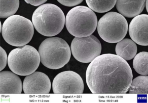
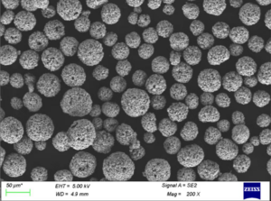
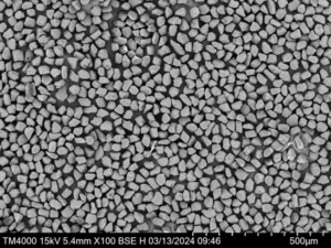
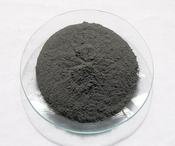
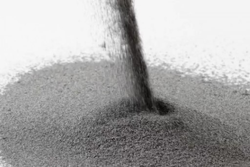
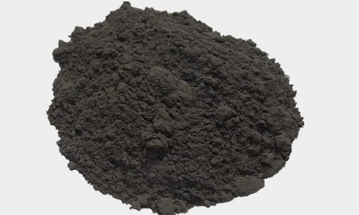
- Feedstock preparation – Metal powder is mixed with a binder material to create a homogeneous feedstock. This mixture is pelletized for use in the injection molder.
- Injection molding – The feedstock is melted and injected into a mold tool to form the desired “green” shape. Standard injection molding equipment is used.
- Debinding – The binder material is extracted from the molded component through chemical, thermal or catalytic means. This leaves a “brown” part.
- Sintering – The debound parts are sintered to fuse the metal powder into a dense end-use part. The parts shrink during sintering.
Secondary operations like machining, joining, plating and etching can further enhance the components. The basic MIM process flow is shown below:
Table 1: Overview of MIM Additive Manufacturing Process
| Step | Description |
|---|---|
| Feedstock Preparation | Mixing of metal powder and binder into a pelletized feedstock |
| Injection Molding | Molding feedstock into desired green shape |
| Debinding | Removing the binder to leave a brown part |
| Sintering | Fusing of metal powder into final part via heat |
Applications of MIM Parts
MIM is suitable for manufacturing small, complex, net shape metal components in medium to high volumes. Typical MIM applications include:
Table 2: Applications of MIM Additive Manufacturing
| Industry | Example Components |
|---|---|
| Automotive | Fuel injector nozzles, spur gears, turbocharger parts |
| Aerospace | Turbine blades, impellers, initiators |
| Medical | Orthodontic brackets, scalpel handles, forceps |
| Consumer | Watch components, grills, decorative parts |
| Industrial | Knife blades, locking mechanisms, valves |
| Firearms | Triggers, hammers, safeties, slides |
MIM enables consolidation of parts, weight reduction, better performance and lower manufacturing costs across many industries. The mix of geometrical freedom and productivity make MIM suitable for end-use production.
Compared to CNC machining, MIM allows more complex shapes to be mass produced. Minimizing assembly steps through part integration is made feasible with MIM.
Advantages of MIM Additive Manufacturing
MIM has unique benefits that make it a popular manufacturing choice:
Table 3: Advantages of MIM Additive Manufacturing
| Benefit | Description |
|---|---|
| High Volume Production | Up to millions of parts can be produced per year via MIM |
| Low Cost per Part | Reduction in cost with higher production volumes |
| Design Flexibility | Complex geometries and microfeatures are possible |
| Range of Materials | Most alloy powders like stainless steel, tool steel and titanium can be used |
| Good Mechanical Properties | Near full density and uniform composition |
| Variety of Finishes | Machining, etching, plating and other finishes can be applied |
| Established Process | Standards, databases, years of experience available |
The combination of design freedom, material capabilities and cost effectiveness gives MIM advantages over other processes like metal 3D printing, investment casting or machining.
Parts can be engineered with thinner walls, undercuts, hollow interiors and other complex elements. Consolidating multiple components into one MIM part is also feasible.
Limitations of MIM Additive Manufacturing
While having many benefits, MIM does have some constraints:
Table 4: Limitations of MIM Additive Manufacturing
| Limitation | Description |
|---|---|
| Part Size | Typically limited to smaller components of up to 70 cubic inches |
| Low Ductility Materials | Some ductile alloys like aluminum are not readily MIM’able |
| Upfront Costs | Significant tooling investment needed for molds |
| Low Mix Production | Best suited for medium to high volumes of the same part |
| Post Processing | Additional machining or finishing may be needed |
MIM has geometry limits since it involves molding. Thermoset plastics allow larger MIM parts but have lower strength.
Not all metal alloys can be easily formulated into MIM feedstocks. Ductile materials in particular present challenges.
Hard tool steel molds must be fabricated for each new part design. This adds time and cost.
Frequent design changes are less suitable for MIM due to the fixed mold tools. Other 3D printing methods allow easier iteration.
Depending on final dimensional and surface requirements, post molding operations may be needed.
MIM Design Considerations
MIM allows geometrical freedoms but parts must be designed with the process limitations in mind:
Table 5: MIM Design Considerations
| Parameter | Guideline |
|---|---|
| Wall Thickness | Minimum 0.3mm, maximum 5mm. Uniform thickness is ideal |
| Tolerances | ±0.5% is typical but depends on geometry |
| Surface Finish | As-sintered is around Ra 10-15 microns |
| Draft Angles | >1° draft angles required to aid demolding |
| Shape Complexity | Consolidating parts or optimizing topology is feasible |
| Features | Fine details like 0.1mm holes and slots are possible |
| Textures | Complex in-mold textures can be incorporated |
| Inserts | Incorporating other inserts in the mold is possible |
| Weight Reduction | Hollowing, reducing mass through lattices and topology optimization |
The molding process imposes certain design rules. But MIM can still produce geometries unachievable by other methods.
MIM Material Options
A wide range of alloys, including highly demanded steels and titanium, are available for MIM:
Table 6: MIM Material Options
| Material | Applications |
|---|---|
| Stainless Steel | Medical, marine, consumer products |
| Tool Steel | Cutting tools, molds, wear parts |
| Low Alloy Steel | Automotive, machinery components |
| Titanium Alloys | Aerospace, medical implants |
| Nickel Alloys | Aerospace turbines, marine hardware |
| Tungsten Heavy Alloys | Radiation shielding, vibration damping |
High strength, corrosion resistant stainless steel such as 17-4PH and 304L are commonly used. Precipitation hardening grades allow further strength enhancement.
Tool steels like H13 are ideal for forming, stamping and injection molds needing good hardness, toughness and thermal stability.
Titanium alloys for bio-compatibility, nickel alloys for heat resistance and tungsten alloys for density are readily MIM’able.
New materials like MIM copper and aluminum alloys are also under development.
MIM Design Software Options
To assist with MIM design requirements, CAD and topology optimization software options exist:
Table 7: MIM Design Software Options
| Software | Description |
|---|---|
| SolidWorks | Popular CAD with moldflow analysis plugins |
| Autodesk Moldflow | Dedicated injection mold simulation |
| nTopology | Topology optimization and design for AM software |
| Materialise 3-matic | Tool for designing lattices and lightweight structures |
| Netfab | Software for optimizing 3D meshes for MIM |
Solidworks is commonly used for CAD design. The moldflow simulation can check manufacturability.
Specialized programs like Moldflow add advanced analysis and process modeling capabilities.
Topology optimization software like nTopology allows organic shapes tailored for AM and MIM. Lightweighting and consolidation are enabled.
Software like 3-matic helps design variable density lattices and generate support structures.
MIM Process Parameters
MIM involves optimizing feedstocks, molding, debinding and sintering. Typical parameters are:
Table 8: MIM Process Parameters
| Step | Typical Range |
|---|---|
| Powder Size | 5 – 25 microns |
| Binder | 30 – 50% of feedstock volume |
| Solids Loading | 55 – 70% in feedstock |
| Mold Temperature | 150 – 185°C |
| Injection Pressure | 60 – 110 MPa |
| Molding Cooling Rate | 20 – 50°C/s quenching |
| Debinding Method | Solvent, thermal, catalytic |
| Debinding Time | Days to hours |
| Sintering Temperature | 50 – 80% of melting point |
| Sintering Time | Hours to days |
| Shrinkage | 13 – 17% linear shrink |
The parameters depend on material, part geometry, production rate and properties needed.
Fine powders and high solid loadings aid resolution. Faster cooling and mold temperatures create better green strength. Lower debinding times and higher sintering temperatures increase production rates.
MIM Post Processing Options
As sintered MIM parts may require additional processing:
Table 9: MIM Post Processing Options
| Process | Purpose |
|---|---|
| Heat Treatment | Change microstructure for enhanced properties |
| Plating | Apply decorative coatings like gold or chrome |
| Passivation | Create protective oxide layer on steels |
| Welding | Join MIM parts to each other or other components |
| Laser Marking | Permanent marks for logos, text or ID codes |
| Machining and Drilling | Higher precision dimensions or custom features |
| Vibratory Finishing | Smoothen surface and round sharp edges |
Post molding steps can refine appearance, properties and interfaces to other components. Plating, anodizing and painting are popular finishes.
Connecting MIM parts via welding, brazing or gluing may be required for some assemblies. Additional machining can create precision mating surfaces.
MIM Equipment Suppliers
Established injection molding companies offer MIM equipment and services:
Table 10: MIM Equipment Suppliers
| Company | Equipment |
|---|---|
| ARBURG | Electric and hydraulic injection molding machines |
| Milacron | Complete integrated MIM lines |
| Toshiba | Hybrid and electric molding machines |
| Netstal | High precision injection molding |
| Nissei | Vertical and horizontal injection molders |
| Sodick | High speed, high frequency molding |
Specialized MIM services are also available from:
- PIM International
- MPP
- MIMITAL
- CN Innovations
These full service providers offer feedstock formulation, analysis, tooling, molding, debinding and sintering.
Cost Considerations for MIM Additive Manufacturing
MIM has relatively high startup costs but low per part costs at production volumes:
Table 11: MIM Cost Considerations
| Cost Factor | Typical Range |
|---|---|
| Mold Tool | $10,000 – $100,000+ depending on complexity, material and size |
| Small Batch Setup | Under $10,000 |
| Incremental Part Cost | $0.5 – $5 metal cost per piece |
| Production Rate | 5,000 – 500,000 parts per year per tool |
| Finishing | $0.1 – $2 per part depending on process |
| Batch Size Breakeven | 1,000 – 10,000+ parts vs other processes |
Milling an MIM mold tool from tool steel can take weeks and cost over $100,000 for large components. Smaller less complex molds can be under $10,000.
Once the mold is made, ongoing MIM process costs are very economical for medium to high production volumes. MIM can produce up to one million parts annually from a single mold tool.
Choosing Between MIM and Other AM Processes
MIM is positioned between 3D printing and high volume processes:
Table 12: Comparing MIM and Other Metal AM Processes
| Factor | MIM | Binder Jet 3D Printing | DMLS | Die Casting |
|---|---|---|---|---|
| Capital Cost | High for tooling | Medium | High | Very High |
| Per Part Cost | Lowest above 10k parts | Low at low volumes | Medium | Lower at very high volumes |
| Materials | Wide range of alloys | Limited range | Limited range | Aluminum and zinc alloys |
| Resolution | Medium ~0.1 – 0.3mm | Medium ~0.3 – 0.5mm | Highest ~0.05mm | Lower ~0.5mm |
| Production Speed | High | Medium | Slow | Very High |
| Post Processing | Medium | High | Medium | Low |
| Mechanical Properties | Good | Variable | Best | Good |
| Design Constraints | Some geometrical constraints | Few constraints | Some overhang constraints | High level of constraints |
MIM provides the best economics for complex geometries in alloy materials needed at productions of 10,000+. Lower cost mass production processes become favorable at much higher volumes.
Conclusion
MIM is an attractive metal additive manufacturing process enabling complex geometries to be mass produced directly in a range of engineering alloys.
It combines the versatility of AM with productivity approaching conventional manufacturing. This powerful fusion leads to lower part costs, consolidation of assemblies, better performance and lightweight construction.
While needing some initial mold investment, MIM delivers valuable economies of scale. It is establishing itself as a complementary technique bridging the gap between prototype 3D printing and high-volume manufacturing.
Continued materials development and software integration will expand MIM applications across medical, aerospace, automotive, industrial and consumer sectors.
MIM Additive Manufacturing – FAQ
Q: How does MIM compare to die casting?
A: MIM can produce more complex, higher precision geometries than die casting but has lower production rates and volumes. Die casting is faster and cheaper for simpler shapes needed in the millions.
Q: What size parts can be made with MIM?
A: MIM parts typically range from 0.5 grams to 70 grams in weight. Larger components up to 250 grams are possible with equipment to handle higher pressures and tooling sizes.
Q: What determines the cost of a MIM mold tool?
A: Mold material, complexity, size, surface finishes, and turnaround time affect mold fabrication costs. Simple tool steel molds can be under $10k while large production hardened steel molds can exceed $100k.
Q: Does MIM require any post processing?
A: Some applications need additional heat treatment, machining, or surface finishing. But many components can be used as-sintered. Post processing depends on final dimensional and appearance requirements.
Q: How many parts can a MIM mold produce?
A: MIM production rates typically range from 5,000 to 500,000 parts annually per tool. With proper maintenance, millions of shots are possible over years of service life.
Q: What are common MIM design errors to avoid?
A: Insufficient draft angles, severe undcuts, thick to thin wall transitions and placing fine details on opposite sides of a core can all cause molding issues. Consulting with experienced designers is recommended.
Q: Can multiple materials be combined in MIM?
A: Yes, MIM enables multi-material parts by using powder mixtures or multiple feedstocks. Insert molding with other alloys or hard materials is also possible for composite structures.
Q: How is surface finish of MIM parts?
A: The as-sintered finish is around 10-15 microns roughness. This is suitable for many applications. Additional tumbling or polishing can further smooth surfaces if needed.
Q: How long does the MIM process take?
A: Lead times range from 6-12 weeks typically. Mold fabrication takes the most time if required. Once tools are made, batch production is quite fast for small components.